 Eileen Yu, Vice General Manager
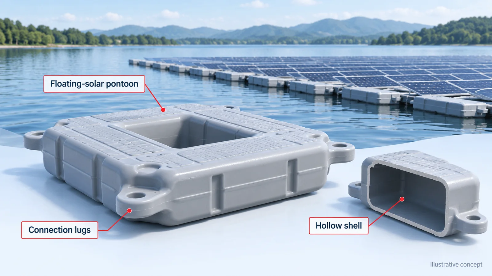
Blow molded floating-solar pontoons need a defined shell geometry, reliable connections, controlled wall distribution and tests appropriate to the installation. Buoyancy comes from water displacement relative to the total supported mass. Wall distribution affects the float’s own mass, structure and durability; it is not a stand-alone measure of array capacity or safety.
Tongda’s TDBX-3000A source case describes large hollow-part production for an overseas floating photovoltaic project. It provides equipment and cycle context, while each new float design still requires its own process and system qualification.
Define the float within the complete system
Supply the float drawing and identify connection lugs, mounting points, sealing features and handling surfaces. Specify the supported equipment and the loads that the system designer requires the float and its connections to withstand. Include the environmental conditions and intended service requirements in the product brief.
A blow molding supplier can evaluate the manufacturing route for the hollow component. The complete floating structure also involves connectors, anchoring and installation-specific design. A successful shell-production trial does not replace that work.
Control the critical sections and sealing features
Map wall measurements around corners, connections, broad panels and the pinch-off. Inspect local sections as well as total part mass. An acceptable average weight can hide a thin connection region or a weak seam.
Agree how leakage, dimensions and repeatability will be checked. Retain conditioned samples and link them to the resin batch, mold and recipe. Compare repeated parts rather than assuming that one successful float proves a long production run.
Read the TDBX-3000A figures as a case configuration
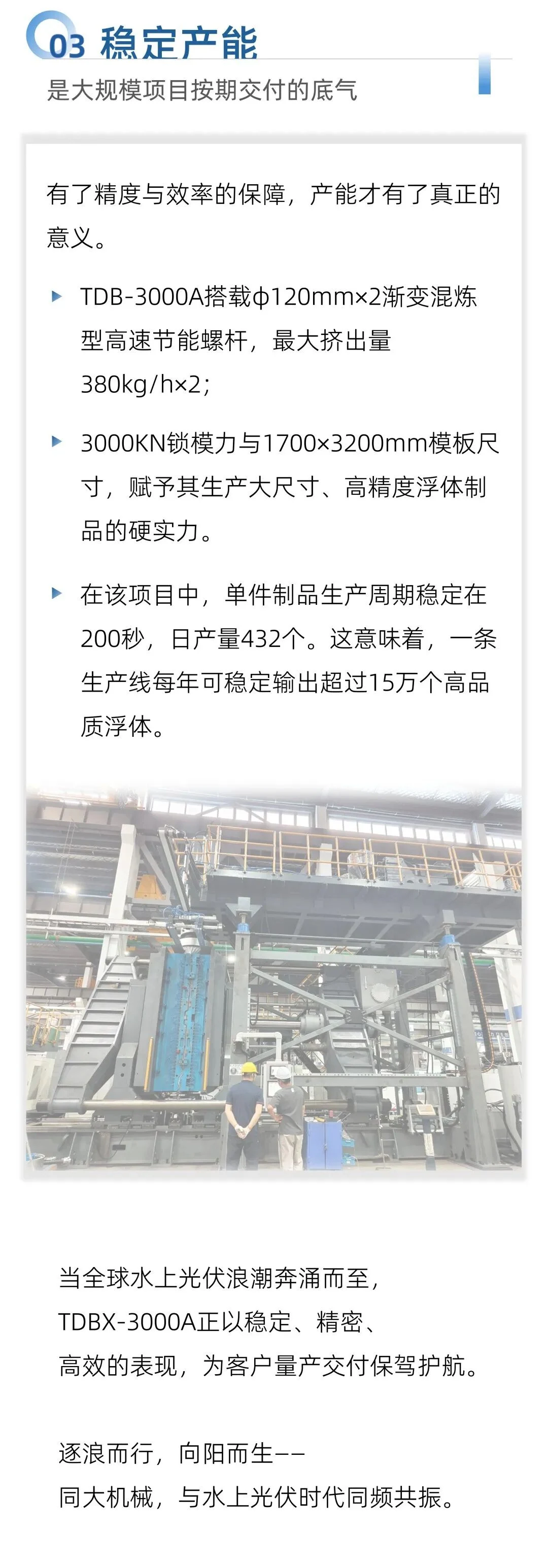
| Source-reported item | How to use it in a new project |
|---|---|
| Part mass around 13–15 kg | Check the new drawing, material and wall requirements |
| 3,000 kN clamping force | Review the actual mold and clamping arrangement |
| 1,700 × 3,200 mm platens | Verify mounting, tool envelope and motion clearances |
| Two 120 mm screws | Confirm resin throughput under the intended conditions |
| Around 200 seconds per part | Confirm the complete cycle and accepted-output basis |
The source also reports a maximum extrusion figure of 380 kg/h per screw. Maximum plasticizing capacity is not a direct measurement of accepted floats per hour: tooling, shot demand, cooling and the full sequence also constrain production. Keep this case separate from the specifications of other TDBX machines.
Convert the cycle into a realistic production plan
One part every 200 seconds gives a theoretical rate of 18 parts per hour, or 432 parts in 24 uninterrupted hours. Annual output cannot be determined without production days, operating hours, availability and accepted yield.
Include mold changes, resin or color changes, planned maintenance, trimming and handling. Large parts may require substantial space between molding and packing. Check whether those operations can support the proposed delivery schedule before using theoretical output in a quotation.
Prepare a product-specific trial
Agree the resin, additives, mold, local-wall locations, dimensional tolerances, leakage checks and any required conditioned-product tests. Record utility conditions and the time used to complete the full process. If a new material or design is proposed, review it against the same acceptance criteria.
For a family of floats, identify the demanding cases rather than assuming that a trial on one geometry proves all of them. Connections, deep corners and different projected areas can change the manufacturing requirements.
Questions buyers ask
Does a thicker float automatically support a larger payload?
No. Additional wall material also adds self-weight. Evaluate the geometry, displacement, total supported load and structural requirements together.
Can the same machine make other large hollow parts?
Potentially, if the tool, shot requirement, material and handling arrangement are compatible. Each application needs a configuration review.
Read the accumulator-head selection guide and large running-board case, then send a pontoon drawing and output requirement.
Adapted from Tongda’s original WeChat article. Case figures are manufacturer-reported for the described application. Original photographs and English concept illustrations are identified in their captions.