 Eileen Yu, Vice General Manager
Physical foam blow molding introduces gas into the polymer process to create a cellular wall structure. For an automotive HVAC duct, the useful comparison is the complete duct at a defined duty: mass, dimensions, airflow, thermal behavior, acoustics and mechanical performance. Lower density alone does not prove that all of these improve.
Tongda’s source article presents the TDB-50K as a physical-foaming blow molding configuration for duct applications. The engineering task is to match the resin, gas system, die, mold and cooling conditions to an accepted component design.
Understand what changes in a foamed wall
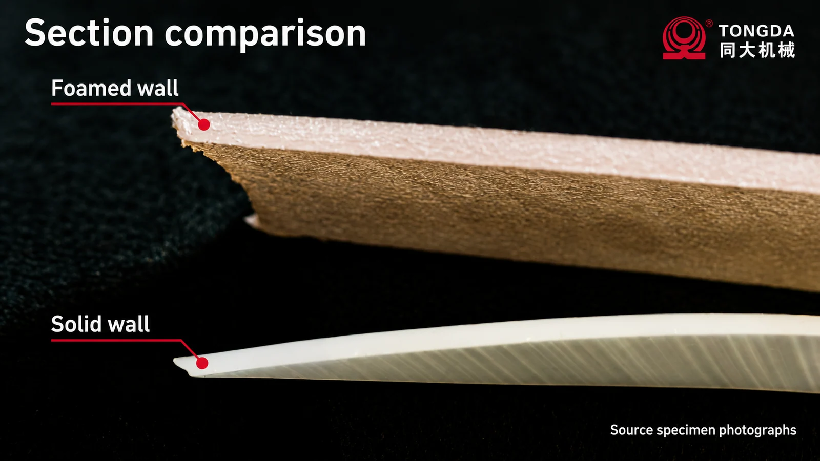
A foamed structure contains cells within the polymer wall. The resulting density and properties depend on the material, gas introduction, pressure history, forming conditions and cooling. Cell size, distribution and the surrounding solid regions matter alongside the overall wall thickness.
A section photograph can illustrate the difference from a solid wall, but it cannot establish a weight-saving percentage or mechanical rating. Compare specimens from defined locations and document how they were prepared and measured.
The technology is used in blow molding beyond this Tongda example: Trexel’s blow molding overview discusses automotive HVAC applications. That establishes application context, not a measured result for the TDB-50K or a claim that the two systems are identical.
Keep thermal, acoustic and mechanical tests separate
A duct may need to meet several targets that do not move in the same direction. A material change can affect stiffness, installation behavior and sound transmission differently. State the test and reference design behind each claimed improvement.
| Requirement | Comparison to define |
|---|---|
| Mass | Complete finished duct at the same functional specification |
| Thermal behavior | Wall structure and test boundary under stated conditions |
| Condensation | Surface temperature, humidity and the complete installation |
| Acoustics | The measured sound or vibration response, not a generic “quietness” claim |
| Mechanical function | Attachment, impact, deformation and service-temperature requirements |
Condensation depends on the relationship between the surface temperature and local dew point. Foaming is one design input; it does not by itself guarantee that no condensation occurs. Likewise, sound absorption, sound insulation and vibration damping should not be presented as the same property.
Specify the offered foaming configuration
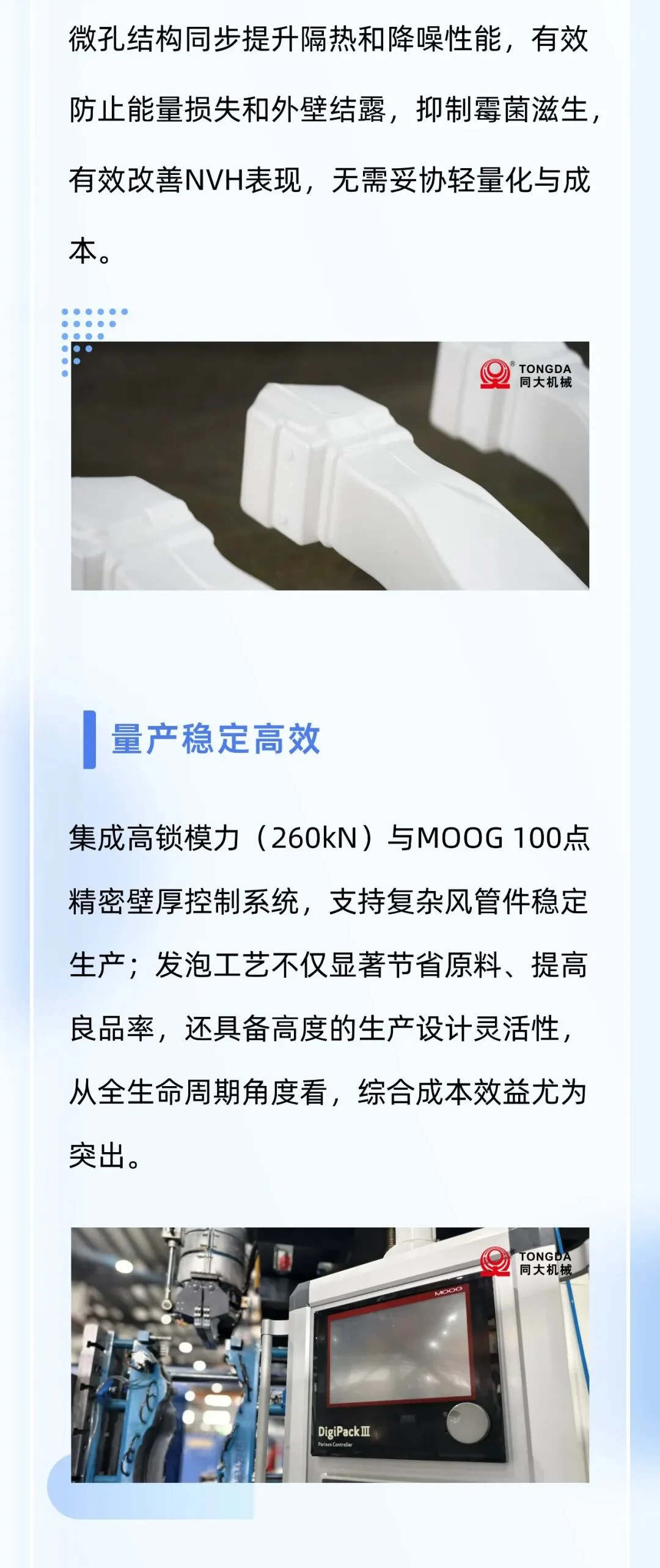
Ask for the current machine configuration, the intended resin and gas, the control functions and the tooling scope. The source lists equipment parameters, but a buyer should confirm the exact supplied arrangement rather than applying those figures to every physical-foaming project.
Review how material is plasticized, how gas introduction is controlled, how the parison is delivered and how the tool removes heat. Agree how process stability will be recorded during the trial. Machine settings are inputs; accepted section structure, geometry and performance are the results.
Physical foaming avoids a chemical blowing agent in that foaming step. This does not prove that the complete material contains no additives, generates no emissions or is compatible with every recycling route.
Run a comparison that answers the purchasing question
Use the intended duct design or a documented reference design. Record material, net part weight, local sections, cycle definition and rejects. Measure energy over a stated boundary if energy cost is part of the decision, including the relevant auxiliary systems.
Retain samples after the agreed conditioning period and test them in the intended assembly where necessary. A result from a simple specimen should not automatically be transferred to a long duct with bends, joints and mounting points.
Questions buyers ask
Can I replace a solid duct with the same geometry in foamed material?
A trial and design review are needed. Changing density and wall structure can change stiffness, joining and dimensional behavior even when the outer shape remains the same.
Which information makes an enquiry useful?
Send the duct drawing, current material and weight, performance targets, reference test results and required output. Identify which targets are mandatory and which are cost-reduction goals.
See automotive-part blow molding and mold design considerations, then request a duct-process review.
Adapted from Tongda’s original WeChat article. Case figures are manufacturer-reported for the described application. Original photographs and English concept illustrations are identified in their captions.